Assembly Notes for Model 1113 & 1115 Kits
Tools Required for 1113u/k & 1115u/k:
Needle Nose Pliers
Xacto knife or other sharp cutter
Wire Stripper
Soldering Equipment
Small Philips Screwdriver
Side/Wire Cutter
For Models 1113t/k, 1113et/k, 1115t/k and 1115et/k you will also need:
A 7/16ths open end wrench is required for studs, locking nuts and Nylok nuts
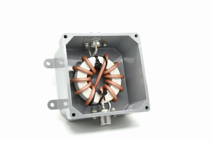
Install connector(s) using the short (3/8ths) machine screw on the left side, the longer (716ths) screw will be used later for the shield ring terminal. Next use an Xacto knife or sharp box cutter and the short piece of coax we included to get a feel for how much force is required to score the jacket but not cut through the shield mesh. You should score (not cut) all the way around the jacket at the 1" mark being careful not to cut through the shield wires. Then run a longitudinal cut from the 1" score to the end of coax which will allow you to peel off the outer sheath covering.This needs to be an actual cut to the outer side of the shield mesh and again being careful not to dig in too much which can damage the shield.
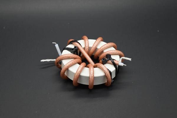
The stripped end of the coax can then be lashed to the toroid with two small zip ties crisscrossed over the coax leaving the 1 inch of bare shield hanging over the edge of the toroid. The two crossed zip ties are important and should not be changed. Please refer to the pictures below to better visualize how the zip ties are positioned.


Begin winding five turns on one side, crossover and then 5 turns on the other side. A turn is defined by the coax passing through the area inside of the toroid. The coax we use is mil-spec and has a silver flashed, copper clad steel center conductor. This combined with the Teflon center insulator makes the cable very springy so it is important to maintain pressure on the coax turns as you wind so the windings are not too loose. After the last turn, lash the coax once again using two zip ties crisscrossed over the remaining coax. After completion move windings for even separation and by also binding the last turn on both sides with another small zip tie.
Please refer to the pictures of each model for a guide and if you do not finish with a minimum of 1 to 2 inches of coax on the output side, the turns are too loose.
When the toroid is fully wound and lashed to the other side of the toroid, remove the coax sheath. The amount of coax to be stripped will be based on the model you are building. Please refer to the suffix types referenced below for the correct length.
This end should be stripped in the same manner as before and the jacket should not extend beyond the short vertical side of the toroid. Pushing the exposed braid toward the toroid forcing it to bunch up which will make it easier to separate. Split the shield to the left with a sharp pointed tool like a scratch all, soldering tool etc and finish by twisting the shield into a single conductor. Ideally and before soldering, ring terminals should be crimped on the conductor with a crimping tool but pliers will also do a good job.
The SO-239 is mounted to the enclosure using a 3/8ths inch pan head machine screw and a lock nut. Leave the mounting hole on the right side of the connector open for the shield connection when the core assembly is installed.
The center conductor of the coax to the SO-239 should be stripped approx 1/8th inch from the twisted shield. You can form the shield lead as we show in the model 1115 picture and use the long thin ring terminal on one end by forming an "L" shape approximately 3/8th inch on a side before crimping and soldering the long thin ring terminal to it. Bend the ring terminal 1/8th of an inch above the soldering tube for connection to the SO-239.
For the "u" configuration (dual SO-239s) the other coax end should be cut to 7/8ths inch with the shield on the left (as you view from above) and a small ring terminal attached. The center conductor should be stripped about 3/16 of an inch from the end. After splitting the shield mesh, twist the entire shield in to a single conductor to the left of the center conductor. Bend the shield and center conductor up 90 degrees and then bend the part of the stripped center conductor back 90 degrees where it will insert into the soldering cup of the SO-239. Finish by installing one of the longer 4-40 pan head machine (7/16ths) screws for each of the shield connections.
For the "t" configuration (studs on top) Cut the coax to a length of 1 1/8th inch and split the shield to the right (as viewed from above) and twist into single conductor. Now attach a large ring terminal to each conductor and insert a 1/4" inch stud through the ring terminals and the two holes opposite the SO-239. On the outside install a washer and locking nut to secure the studs. Studs require a 7/16ths wrench to hold bold head on the inside while outer locking nut is tightened.
For the "et" configuration This variation includes small black tie downs for the zip ties that stabilize the wound core. They should be mounted as shown in the picture above using the two screws with the broad flat head (truss head) and a lock nut. Next trim the coax end opposite the SO-239 to a length of 2 inches, split the shield to the right and then attach the 1/4" ring terminals without the cut notch. Install the wound core in the enclosure soldering the center conductor and screwing down the shield,s small ring terminal. Now insert the eyebolts through a washer, then through the enclosure and the ring terminals attached to the split coax leads securing each with one of the NYLOK nut inside. Both the nut and eyebolt are stainless and subject to "galling" if the nut is turned too fast on the eyebolt. If this occurs the only (and I mean only) solution is to cut the eyebolt off so go slow!! Please don't ask how I know this!!
The very large ring terminals with a cut out notch are used for the antenna wires and are then mounted under the outer locking nut of the eyebolt. Be sure to solder any connections with the ring terminals removed to avoid damaging then enclosure
Do Not Over tighten corners of cover. Leave a gap the thickness of a dime between cover and body. See the Balun and Unun Installation Notes for more information.
