Description
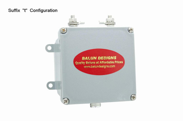
This is a balun originally designed by Guanella and subsequently improved by Dr. Jerry Sevick (W2FMI). By utilizing Thermaleze wire inserted in Teflon tubes, Dr. Sevick was able to substantially increase the breakdown voltage between both conductors and windings while maintaining the required 100 ohm characteristic impedance.
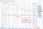
This design utilizes two individual cores wound as choke baluns, each with a 100 ohm characteristic impedance. These two separate baluns are then cross connected to create a 4:1 (200 to 50 ohm) current balun with excellent isolation and high choking impedance and. This balun is also a good choice if you have RFI problems or RF in your shack due to imbalanced ladder line and you want to use a 4:1 impedance reduction to assist your tuner. Please review the scans below to appreciate the excellent specs this balun provides.
Click to Enlarge
All testing done with an AIM-4170c Network Analyzer and precision 200 ohm load
***CAUTION***
When used with a wire antenna, if one or both legs of your antenna will be installed over or close to (< 20 feet) your house, a large structure (garage, barn, etc) or near (< 30 feet) a metal roof/structure and you will be transmitting greater than 700 watts CCS, DO NOT use this 4115 balun. The interaction/coupling of the antenna with the structure and or metal will require high levels of common mode absorption by one ferrite core which will generate excessive heat in the core leading to a change in SWR and possible damage to the balun. Instead use our new Hybrid model 4116 which is not effected by this caution and also incorporates a 1:1 choke balun.
Specifications
| Core Material | Custom mix low permeability ferrite by Fair Rite Products for maximum bandwidth. Large 2.4 inch cores are coated and sealed for long term durability. |
| Winding Type | Individual cores wound with single wire pair as 1:1 current balun. Cores are then cross connected to create 4:1 current balun. |
| Winding Material | Bifilar windings of 14 gauge Heavy build polyamideimide Allex 240 Winding Wire. Windings are inserted in to Teflon tubes for proper impedance and breakdown of 10kv. |
| Power Rating | 1 to 35 MHz - 5kW, 7kW intermittent. 35 to 54 MHz - 4kW. All ratings based on matched condition. High SWR will reduce power handling ability. |
| Useable Frequency | 1 to 54 MHz |
| Insertion Loss | Less than 0.2db |
| Connectors | SO-239 connectors are gold center conductor with Teflon insulation. Studs and eyebolts are 1/4 inch. Alternate connectors and Mounting Options are available in the Accessories section. |
| Hardware | All Stainless Steel |
| Enclosure Type |
NEMA rated 4x marine grade junction box for outdoor installations. Cover utilizes integral neoprene gasket for weatherproof integrity. |
| Dimensions | 4x4x2 inches for main body of unit Dimensional Drawing of Standard Enclosure |
| Additional Info | Very high efficiency (98-99%) Weight 1lb 6oz |


